

الاحتفاظ بالحمل المسبق لتوربينات الرياح تحت التحميل الدوري
في مراجعات الفشل لهياكل دعم الطاقة المتجددة، غالبًا ما أرى ملحقًا للبرج أو مفصل إطار المعدات يستقر بعد التثبيت ويبدأ في الفتح تحت الحمل المتكرر الذي تحركه الرياح. قد يبدو الضرر النهائي وكأنه أداة تثبيت مكسورة، لكن التسلسل الهندسي يبدأ مبكرًا - بالهوية المادية، أو هندسة المفاصل، أو سلامة التصنيع، أو سلوك التثبيت، أو بيئة الخدمة المتغيرة. تعمل هذه المقالة على تطوير الاحتفاظ بالتحميل المسبق للترباس من تلك الآلية بدلاً من المطالبات التسويقية.
بيانات المنتج التي تم التحقق منها ضيقة بشكل متعمد: مسمار سداسي من الفولاذ المقاوم للصدأ 904L، M3–M160، قدرة غير قياسية، وتنفيذ وفقًا لـ DIN، أو ANSI، أو GB، أو رسم غير قياسي معتمد. لا يتم توفير فئة القوة، أو الحمل المضاد، أو قيمة الشد، أو الصلابة، أو معامل عزم الدوران، أو حد التعب، أو قيمة عمر التآكل، أو الطلاء، أو مجموعة التسامح، أو الرقم القياسي الدقيق. تحقق من كل معلمة مفقودة مقابل تقرير الاختبار الحالي الخاص بالشركة المصنعة قبل المواصفات.
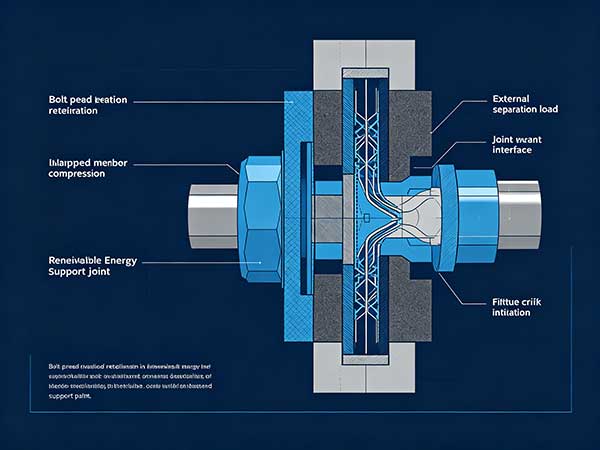
أقوم بتصميم المفصل كنظامين مرنين: مثبت الشد والأعضاء المضغوطة. يعمل التشديد على تحريك كلا النظامين بعيدًا عن حالة التفريغ. تقوم قوة الفصل اللاحقة أولاً بتحرير ضغط العضو وتزيد فقط من شد المثبت جزئيًا بينما تظل الواجهة مغلقة. إذا تم فتح الواجهة، ينهار قسم التحميل المفيد هذا. يتلقى الترباس بعد ذلك حملًا متناوبًا أكبر وعادةً ما يكون مكون الانحناء غائبًا عن الحساب الاسمي.
يشرح هذا النموذج لماذا لا يكون القطر الاسمي أبدًا مدخلاً كاملاً للتصميم. يحدد طول القبضة، وصلابة العضو، وامتثال وجه المحمل، ومشاركة الخيط، وطلاءات الواجهة، والغسالات، وغرابة التحميل كيفية تقسيم القوة الخارجية. أي مراجعة تتعامل مع أداة التثبيت كقضيب شد معزول تفتقد آليات المفصل السائدة.
في الحالة الحالية، إجراء الخدمة الحاكم هو الفصل المحوري الدوري مع الاهتزاز والانحناء الثانوي العرضي. أود أن أقوم بتخطيط هذا الإجراء من الأعضاء المثبتة من خلال وجه المحمل، والانتقال من الرأس إلى الساق، والساق، والخيوط المتشابكة، ومكون التزاوج. يجب أن تحدد الخريطة المكان الذي يمكن أن يفتح فيه الاتصال، وأين يمكن أن يبدأ الانزلاق، وأين يظهر الانحناء المحلي أو تركيز الإجهاد. ويحدد هذا التمرين الأبعاد والعيوب التي تعتبر بالغة الأهمية حقًا.
تحديد الهندسة المفرغة.سجل الفجوات ووجوه التلامس وموضع الخيط والمشاركة الفعالة والمحاذاة.
تعريف التثبيت.اذكر كيفية إنشاء قوة المشبك وقياسها والاحتفاظ بها دون افتراض أن عزم الدوران يساوي التحميل المسبق.
تطبيق إجراءات الخدمة.يشمل الفصل المحوري الدوري مع الاهتزاز والانحناء الثانوي العرضي وأي إعادة توزيع بين المثبتات المجاورة.
تقييم التدهور.ضع في اعتبارك الرطوبة ودورة درجة الحرارة والاهتزاز والوصول المحدود للصيانة كتغييرات في الميكانيكا وحالة المواد وقابلية الفحص.
ربط الأدلة بالقرارات.قم بتعيين عنصر تحكم في الرسم أو اختبار لكل آلية فشل موثوقة.
شهادة نظام إدارة الجودة LY203E5074Q، الصادرة عن Shanghai Liyang Certification Co., Ltd. هي دليل الشهادة الوحيد المقدم. يشير إلى شهادة نظام إدارة الجودة؛ يجب التحقق من الصلاحية الحالية والموقع والنطاق ومعيار نظام الإدارة المشار إليه بواسطة الشهادة قبل استخدام المستند في ملف فني.
تتضمن "المكونات" ذات الصلة مناطق هندسية وواجهات تزاوج لأنه لا يمكن التحقق من صحة المسمار بشكل منفصل. بالنسبة لهياكل دعم الطاقة المتجددة، يتم تحديد المجموعة الحرجة من خلال المسار الذي يدخل من خلاله الفصل المحوري الدوري مع الاهتزاز والانحناء الثانوي العرضي إلى التجميع. يفصل الجدول المعلومات التي تم التحقق منها عن تعريفات المشروع حتى يتمكن المهندس من معرفة أين لا تزال الأدلة مفقودة.
| عنصر | تعريف تم التحقق منه أو مطلوب | الوظيفة الهندسية | خطر إذا تم اختراقه |
|---|---|---|---|
| الترباس مسار مادة الاحتفاظ التحميل المسبق | الفولاذ المقاوم للصدأ 904L | يحافظ على الافتراض المادي المستخدم في هياكل دعم الطاقة المتجددة | مزيج المواد يقطع العلاقة بين التحقق من الصحة والإنتاج |
| الهندسة المحددة ضمن M3 – M160 | مطلوب رسم دقيق يتم التحكم فيه | يحدد موقع واجهات الرأس والساق والخيط والتزاوج في مسار التحميل المقصود | يدخل الحمل الخارجي إلى الترباس بشكل أكثر مباشرة ويرفع نطاق الضغط |
| خاصية التحكم بفصل الواجهة | رسم هندسي محدد وحالة السطح | يمنع أو يكشف الحالة: التضمين المتراكم وعدم كفاية الامتداد المرن الأولي | يدخل الحمل الخارجي إلى الترباس بشكل أكثر مباشرة ويرفع نطاق الضغط |
| ميزة التحكم في تعب الخيط الأول | واجهة التزاوج المحددة حسب المشروع أو حالة العملية | يمنع أو يعرض الحالة: يتحد الفصل مع مشاركة غير متساوية لتحميل الخيط | ينمو الكراك من الجذر المنخرط الأول |
| خاصية التحكم في الانحناء تحت الرأس | رسم هندسي محدد وحالة السطح | يمنع أو يعرض الحالة: سطح التحمل ليس متعامدًا مع محور الترباس | يحمل جانب واحد من الشرائح ضغطًا متناوبًا أعلى |
| ميزة التحكم في التخفيف بمساعدة الحنق | واجهة التزاوج المحددة حسب المشروع أو حالة العملية | يمنع أو يكشف الحالة: يزيل Microslip الأفلام السطحية ويغير الاحتكاك | قوة المشبك وتصلب المفاصل تصبح غير مستقرة |
تحقق من جميع المعلمات مقابل تقارير الاختبار الحالية والمعايير المعمول بها قبل استخدامها في المواصفات.
لا تحل المادة الاسمية والقطر هندسة الانتقال، أو تسامح الخيط، أو العلاقة بين الوجه والوجه، أو سلوك خيط التزاوج. يجب التحكم في هذه الميزات في تسلسل هرمي واحد للرسم بأسبقية واضحة. عند استدعاء عائلة قياسية، يجب أن يكون أي خروج غير قياسي مرئيًا وليس مخفيًا في ملاحظة عامة.
أستخدم مصفوفة الأدلة بدلاً من قائمة التفتيش العامة. يجب أن يوضح كل صف الخاصية، وسبب أهمية تثبيت الاحتفاظ بالتحميل المسبق، ومرحلة الإنتاج التي تنشئه، وطريقة التحقق، وقاعدة القبول، وتكرار أخذ العينات أو الفحص، وخطة التفاعل، والسجل المحتفظ به. القيم الغائبة عن الملحق تظل مفتوحة؛ ويجب ألا تكتمل من الذاكرة أو من درجة تثبيت أخرى.
| المعلمة | طريقة التحقق | النطاق أو الحالة المقبولة | معنى الهندسة |
|---|---|---|---|
| الهوية المادية النهائية | شهادة المادة الحالية بالإضافة إلى طريقة الهوية المعتمدة | الفولاذ المقاوم للصدأ 904L | سبيكة لم يتم التحقق منها تبطل الافتراضات المادية |
| الحجم الاسمي المحدد | معايرة الأبعاد التفتيش | M3 – M160 هو النطاق المتوفر؛ حدد وتحقق من حجم واحد | لا يمكن لحسابات الملاءمة والتحميل استخدام حجم غير محدد |
| معيار التنفيذ | مراجعة المستندات والفحص الخاص بالميزات | DIN أو ANSI أو GB أو رسم غير قياسي معتمد | لم يتم توفير المعرف الدقيق والمراجعة |
| التحقق من فصل الواجهة | تجربة فيزيائية تعيد إنتاج الفصل المحوري الدوري مع الاهتزاز والانحناء الثانوي العرضي | خاص بالمشروع؛ التحقق من صلابة المفاصل وحالة الجلوس والتحميل المسبق المحتجز | قد يؤدي التضمين المتراكم والتمديد المرن الأولي غير الكافي إلى دخول الحمل الخارجي إلى البرغي بشكل مباشر أكثر وزيادة نطاق الضغط |
| التحقق من التعب في الخيط الأول | فحص الأبعاد أو السطح على مستوى الميزة | خاص بالمشروع؛ التحكم في المشاركة والمحاذاة وسلامة الجذر والتحميل المسبق | قد يؤدي الجمع بين الانفصال وتقاسم حمل الخيط بشكل غير متساو إلى نمو الكراك من الجذر الأول المتفاعل |
| التحقق من الانحناء تحت الرأس | يعكس اختبار التعرض أو التجميع الرطوبة ودورة درجة الحرارة والاهتزاز والوصول المحدود للصيانة | خاص بالمشروع؛ التحقق من التسطيح والعمودية والجلوس | سطح التحمل ليس عموديًا على محور الترباس مما يؤدي إلى أن جانب واحد من الشرائح يحمل ضغطًا متناوبًا أعلى |
| التحقق من الارتخاء بمساعدة الحنق | مراقبة العمليات وسجل احتواء الدفعة | خاص بالمشروع؛ منع الانزلاق وفحص الواجهات | يقوم Microslip بإزالة الأفلام السطحية وتغيير الاحتكاك قد يؤدي إلى قوة المشبك وتصبح صلابة المفاصل غير مستقرة |
| أدلة نظام الجودة | تحقق من الموقع الحالي والنطاق والصلاحية والمصدر | شهادة نظام إدارة الجودة LY203E5074Q، الصادرة عن Shanghai Liyang Certification Co., Ltd. | يجب أن تدعم السجلات الاحتفاظ بالتحميل المسبق للمسمار، وليس فقط مطالبة عامة للنظام |
تحقق من جميع المعلمات مقابل تقارير الاختبار الحالية والمعايير المعمول بها قبل استخدامها في المواصفات.
DIN وANSI وGB هي عائلات قياسية، وليست تعريفات كاملة للمنتج. يجب على المهندس تحديد المستند الدقيق والمراجعة ونمط المنتج ونظام الخيوط وفئة التسامح ومتطلبات الملكية الميكانيكية وطريقة الاختبار المقصودة بالفعل. يجب أن يحمل الرسم غير القياسي المعتمد هذه المتطلبات بنفسه. لا ينبغي قبول "المعادل" دون مقارنة موثقة لكل عبارة ذات صلة وظيفية.
بالنسبة للاحتفاظ بالحمل المسبق للمسمار، يجب أن يتم اشتقاق نطاقات القبول من مسار التحميل والتجميع المعتمدين. إذا كان المشروع يتطلب التحميل المسبق، أو التعب، أو التآكل، أو التجريد، أو الصلابة، أو عمق الهيكل، أو الدقة البصرية، أو حدود التيار الدوامي، أو أهداف القدرة، فإن هذه الأرقام تتطلب أدلة حالية. ولا يمكن أن تحل المواد الموردة ونطاق الأبعاد محلها.
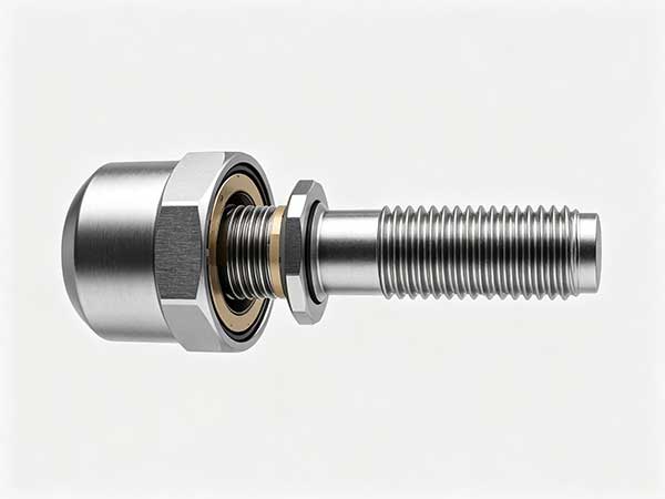
بالنسبة لهذا التطبيق، أبدأ بمتطلبات قوة المشبك المحتفظ بها بدلاً من عزم الدوران الاسمي. يمكن أن تشتمل مجموعة الوصلات على ألواح مطلية، وحشوات، وطلاء، وغسالات، وواجهات ذات صلابة ضغط مختلفة. يضيف التضمين الصغير على عدة أسطح معًا. قد توفر القبضة الطويلة توافقًا مفيدًا للمثبت، لكن هامش الفصل الفعلي لا يزال يعتمد على خصائص الترباس التي تم التحقق منها وصلابة العضو.
التحميل الذي يحركه الرياح متغير في السعة. قد ينفصل المفصل الذي يظل مغلقًا في ظل الدورات العادية خلال حدث عابر ثم يعود إلى الحالة الطبيعية الظاهرة. يمكن أن يؤدي هذا الفتح القصير إلى إثارة القلق أو تغيير توزيع الحمل بين البراغي المجاورة. يجب اختيار أدوات التشديد أو قياس الاستطالة أو أي طريقة تحميل مسبق أخرى تم التحقق منها وفقًا للوصول والدقة؛ البيانات المقدمة لا تثبت واحدة.
يجب أن يميز تخطيط الفحص بين الدوران الناتج عن الارتخاء وفقدان المشبك الناتج عن التسوية. يمكن أن تظهر علامة الشاهد التدوير النسبي ولكن لا يمكنها تحديد التحميل المسبق المحتفظ به. إذا تم اقتراح إعادة الشد، فيجب أن يتناول الإجراء حالة الخيط، وحالة التشحيم، وحدود إعادة الاستخدام، وما إذا كانت الخدمة السابقة قد غيرت الاحتكاك أو أحدثت ضررًا.
فصل الواجهة كشرط تصميمي.في هياكل دعم الطاقة المتجددة، تكون آلية البدء هي التضمين المتراكم وعدم كفاية الامتداد المرن الأولي. سأقوم بإعادة إنتاج الفصل المحوري الدوري مع الاهتزاز والانحناء الثانوي العرضي مع الحفاظ على ثبات هندسة التزاوج وحالة التثبيت، ثم فحص الميزة قبل التحميل وبعده. والنتيجة الهندسية هي أن الحمل الخارجي يدخل إلى الترباس بشكل أكثر مباشرة ويرفع نطاق الضغط. يجب أن يوضح سجل التحقق المفيد سبب مقاطعة التحكم المقترح - التحقق من صلابة المفصل وحالة الجلوس والتحميل المسبق المحتفظ به - لتلك السلسلة المادية بدلاً من مجرد اكتشاف الضرر النهائي.
الأدلة اللازمة لتعب الخيط الأول.يجب أن يبحث التحقيق بشكل خاص عن أدلة على الانفصال مع المشاركة غير المتكافئة لحمل الخيط. قد تتضمن الملاحظات ذات الصلة الاتصال غير المتماثل، أو حركة الأبعاد، أو النقل السطحي، أو أصل الكسر الموضعي، أو سجل العملية الذي تغير قبل الدفعة المتأثرة. نظرًا لأن Crack ينمو من أول جذر مشترك، يجب أن يعتمد القبول على اختبار وظيفي محدد بالمشروع وفحص على مستوى الميزات. الشرط الوقائي هو التحكم في المشاركة والمحاذاة وسلامة الجذر والتحميل المسبق.
حالة الحدود: الانحناء تحت الرأس.يصبح هذا الوضع مهمًا عندما يقوم الإنتاج العادي أو اختلاف الخدمة بتحريك التجميع نحو سطح المحمل وليس عموديًا على محور الترباس. يجب أن تختبر المراجعة المجموعة الأقل مصداقية من الهندسة، وحالة المادة، والاحتكاك، والرطوبة، ودورة درجة الحرارة، والاهتزاز، والوصول المقيد للصيانة. إذا كانت الآلية نشطة، فإن أحد جوانب الشرائح يحمل ضغطًا متناوبًا أعلى. ولذلك يجب أن تتطلب المواصفات دليلاً للتحقق من الاستواء والعمودية والجلوس ويجب أن تحدد الاحتواء عندما يفشل هذا الدليل.
منطق الفحص للتخفيف بمساعدة Fretting.لا يمكن للمظهر المرئي النهائي وحده تأكيد ما إذا كان Microslip يزيل الأفلام السطحية ويغير الاحتكاك. سأختار طريقة فحص تراقب ميزة البدء، وإشارة عملية تحدد متى يمكن إنشاؤها، وتسجيلًا كبيرًا يحد من التعرض. السبب مباشر: تصبح قوة المشبك وتيبس المفاصل غير مستقرة. يجب أن توضح خطة التحكم كيفية منع الانزلاق وفحص الواجهات ومن يتفاعل وأي منتج يظل معلقًا.
التفسير الميداني للتآكل في المناطق المحمية.عند إرجاع المجموعة من الخدمة، يجب على المحلل مقارنة الجزء التالف بالأجزاء غير المستخدمة من نفس الدفعة ومع أدوات التثبيت المجاورة. فرضية العمل هي أن الرطوبة تبقى تحت الغسالات أو الوجوه الحاملة؛ والنتيجة المتوقعة هي القسم المحلي وانخفاض سلامة السطح. يجب أن تدعم سجلات التثبيت وعلامات الاتصال وموقع الكسر والأدلة المادية وعلم الأنساب العملية هذه الفرضية أو ترفضها. يجب أن يؤكد الإجراء التصحيحي هوية 904L والتحكم في الصرف.
يجب أن يتم تصميم التشكيل على البارد كتسلسل بدلاً من وصفه بقدرة الماكينة. يحدد حجم المخزون، وحالة القطع، وهندسة التشكيل، والتشوه المخصص لكل محطة، ومحاذاة النقل، ودعم القالب، والتشحيم، وليونة المادة الفعلية ما إذا كان الرأس والانتقال يمتلئان بدون لفات أو شقوق. يظل السطح الذي يطوي داخل التجويف متقطعًا لأن الضغط لا يعيد إنشاء الاستمرارية المعدنية عبر السطح البيني المؤكسد.
ينبغي أخذ عينات التطوير المقسمة من خلال مسارات التدفق الأكثر تطلبًا. ويمكن بعد ذلك مقارنة اتجاه تدفق الحبوب، والتعبئة تحت الرأس، واستمرارية التحول، وأي سطح مطوي مع تحليل التشكيل. تعتبر المحاكاة مفيدة لتحديد موقع إجهاد الشد العالي وضغط القالب، ولكنها تتطلب الارتباط مع أجزاء الإنتاج في أكثر من نقطة واحدة في عمر الأداة.
لا يكون التحكم في العملية الإحصائية ذا معنى إلا بعد أن يكون نظام القياس والعملية مستقرين بدرجة كافية للتفسير. تحتاج كل خاصية حرجة إلى مجموعة فرعية محددة، وتكرار أخذ العينات، ونوع المخطط، وقاعدة التفاعل، وحدود الاحتواء. إن مؤشرات القدرة ليست بدائل للقبول: فالمؤشر المفضل لا يمكن أن يبرر إشارة لسبب خاص، ولابد من الاتفاق على قيمة مستهدفة للمشروع لأنه لم يتم توفير أي منها في البيانات التي تم التحقق منها.
يجب أن يكون قياس التكرار وقابلية التكرار صغيرًا بما يكفي لتمييز حركة العملية التي تهم التجميع. يمكن للدقة والتركيب ومحاكاة المسند وطريقة التشغيل ودرجة الحرارة ونظافة الأجزاء أن تغير النتيجة. يجب حل خلاف القياس بين المورد والعميل قبل إصدار الإنتاج.
المرحلة 1 - فصل الواجهة:قم بإعداد عينة تجميع أو إنتاج يتم فيها التضمين المتراكم والامتداد المرن الأولي غير الكافي. تطبيق أو محاكاة الفصل المحوري الدوري مع الاهتزاز والانحناء الثانوي العرضي، ثم توثيق ما إذا كان الحمل الخارجي يدخل الترباس بشكل مباشر أكثر ويرفع نطاق الضغط. قم بتحرير المرحلة فقط عندما يظهر الدليل أن التصميم أو العملية سوف تتحقق من صلابة المفصل، وحالة الجلوس، والتحميل المسبق المحتفظ به.
المرحلة 2 - تعب الخيط الأول:قم بإعداد عينة تجميع أو إنتاج يتم فيها دمج الفصل مع مشاركة غير متساوية لحمل الخيط. قم بتطبيق أو محاكاة الفصل المحوري الدوري مع الاهتزاز والانحناء الثانوي العرضي، ثم قم بتوثيق ما إذا كان الكراك ينمو من الجذر المنخرط الأول. قم بتحرير المرحلة فقط عندما يظهر الدليل أن التصميم أو العملية سوف تتحكم في المشاركة والمحاذاة وسلامة الجذر والتحميل المسبق.
المرحلة 3 - الانحناء تحت الرأس:قم بإعداد عينة تجميع أو إنتاج لا يكون فيها سطح المحمل متعامدًا مع محور الترباس. قم بتطبيق أو محاكاة الفصل المحوري الدوري مع الاهتزاز والانحناء الثانوي العرضي، ثم قم بتوثيق ما إذا كان أحد جانبي الشريحة يحمل إجهادًا متناوبًا أعلى. قم بتحرير المسرح فقط عندما تظهر الأدلة أن التصميم أو العملية ستتحقق من التسطيح والعمودية والجلوس.
المرحلة 4 - التخفيف بمساعدة الحنق:قم بإعداد عينة تجميع أو إنتاج يقوم فيها Microslip بإزالة الأفلام السطحية وتغيير الاحتكاك. قم بتطبيق أو محاكاة الفصل المحوري الدوري مع الاهتزاز والانحناء الثانوي العرضي، ثم قم بتوثيق ما إذا كانت قوة المشبك وصلابة المفصل تصبح غير مستقرة. قم بتحرير المرحلة فقط عندما تظهر الأدلة أن التصميم أو العملية سوف تمنع الانزلاق وتفحص الواجهات.
المرحلة 5 - التآكل في المناطق المحمية:قم بإعداد عينة تجميع أو إنتاج تبقى فيها الرطوبة تحت الغسالات أو وجوه التحمل. قم بتطبيق أو محاكاة الفصل المحوري الدوري مع الاهتزاز والانحناء الثانوي العرضي، ثم قم بتوثيق ما إذا كان القسم المحلي وتكامل السطح قد انخفضا. قم بتحرير المرحلة فقط عندما يظهر الدليل أن التصميم أو العملية ستؤكد هوية 904L وتتحكم في الصرف.
يجب أن يستخدم هذا التسلسل الحجم المحدد ومكونات التزاوج الفعلية وحالة سطح الإنتاج والحالة البيئية الموصوفة بالرطوبة ودورة درجة الحرارة والاهتزاز والوصول المقيد للصيانة. وهو ليس بديلاً عن معايير المشروع المطلوبة؛ إنها خريطة الآلية المستخدمة لاختيار الطرق الصحيحة التي تم التحقق منها. تظل قيم القبول خاصة بالمشروع حيثما يكون الملحق المصاحب صامتًا.
يجب أن تكون طبقات التصنيع والفحص متصلة. تتنبأ محاكاة التشكيل بالمخاطر ولكنها لا تطلق المنتج؛ ويثبت التقسيم عينات مختارة ولكنه لا يقوم بفحص مجموعة كاملة؛ تكتشف مراقبة العملية تغيرات الإشارة ولكنها تتطلب ارتباطًا معيبًا؛ لكل من الفرز البصري والتيار الدوامي آليات كشف محدودة. ويجب أن تجمعها خطة التحكم فقط عندما يكون لكل طبقة سؤال محدد وحدود تم التحقق من صحتها.
تمنع هذه الفروق أيضًا النقل غير الصحيح لمطالبات التكنولوجيا. يمكن أن يكون لف الخيط بعد المعالجة الحرارية، والتصلب بالحث، والتشكيل البارد متعدد المحطات، والفرز البصري، وغربلة التيار الدوامي، كلها مفيدة، ولكن لا شيء ينطبق تلقائيًا على كل مسمار سداسي 904 لتر. يجب أن تكون العملية المختارة متوافقة مع المواد والهندسة والأداء المطلوب وأدلة التفتيش للمشروع الفعلي.
| وضع الفشل | السبب الجذري الخاص بالآلية | عاقبة | الوقاية أو الأدلة |
|---|---|---|---|
| فصل الواجهة | التضمين المتراكم والامتداد المرن الأولي غير الكافي | يدخل الحمل الخارجي إلى الترباس بشكل أكثر مباشرة ويرفع نطاق الضغط | التحقق من صلابة المفاصل وحالة الجلوس والتحميل المسبق المحتجز |
| التعب الخيط الأول | يتم الجمع بين الفصل وتقاسم حمل الخيط بشكل غير متساو | ينمو الكراك من الجذر المنخرط الأول | التحكم في المشاركة والمحاذاة وسلامة الجذر والتحميل المسبق |
| الانحناء تحت الرأس | سطح التحمل ليس عموديًا على محور الترباس | يحمل جانب واحد من الشرائح ضغطًا متناوبًا أعلى | التحقق من التسطيح والعمودية والجلوس |
| تخفيف بمساعدة الحنق | يزيل Microslip الأفلام السطحية ويغير الاحتكاك | قوة المشبك وتصلب المفاصل تصبح غير مستقرة | منع الانزلاق وفحص الواجهات |
| التآكل في المناطق المحمية | تبقى الرطوبة تحت الغسالات أو الوجوه الحاملة | القسم المحلي وانخفاض سلامة السطح | تأكيد هوية 904L والتحكم في الصرف |
تحقق من جميع المعلمات مقابل تقارير الاختبار الحالية والمعايير المعمول بها قبل استخدامها في المواصفات.
عندما يستقر ملحق البرج أو وصلة إطار المعدات بعد التثبيت ويبدأ في الفتح تحت حمل متكرر يحركه الرياح، فإنني أحافظ على التجميع قبل التنظيف أو التفكيك. يمكن لعلامات التحمل، وموضع الخيط، والقلق، ورواسب التآكل، واتجاه الكسر، وسجلات الأداة، وحالة التثبيت المجاورة أن تميز آلية البدء عن التحميل الزائد النهائي. قد يؤدي الاستبدال بمسمار أكبر أو أقوى اسميًا إلى تحويل الضرر إلى مكان آخر إذا كان السبب الحقيقي هو اختلال المحاذاة أو التحديق أو التسوية أو الغضب أو خيط التزاوج الذي لم يتم التحقق منه.
يجب كتابة السبب الجذري كسلسلة مادية. "الجودة الرديئة" ليست كافية؛ "السطح المطوي الذي تم إنشاؤه أثناء التشكيل بقي عند الانتقال تحت الرأس وبدأ صدعًا دوريًا بعد أن أدى فصل المفصل إلى الانحناء" هو أمر قابل للاختبار. يمكن لخطة الأدلة بعد ذلك تأكيد أو رفض كل حلقة في السلسلة.
نموذج الفصل المحوري الدوري مع الاهتزاز والانحناء الثانوي العرضي من خلال المكدس الحقيقي المستخدم في هياكل دعم الطاقة المتجددة.
حدد شكلًا هندسيًا واحدًا ضمن M3 – M160 وحدد كل مسند وظيفي وانتقال وخيط ووجه اتصال.
تتطلب أدلة الدفعة النهائية الحالية للفولاذ المقاوم للصدأ 904L؛ لا تقبل وصفًا عامًا غير قابل للصدأ.
قم بتعيين قيم المشروع للقوة، وسلوك الإثبات، والصلابة، والتعب، والتجريد، والتشوه لأن الملحق لا يوفر أي شيء.
فصل الواجهة:التحقق مما إذا كان التضمين المتراكم وعدم كفاية التمديد المرن الأولي؛ تتطلب التحكم في الإنتاج أو التصميم للتحقق من صلابة المفاصل وحالة الجلوس والتحميل المسبق المحتفظ به.
التعب الخيط الأول:التحقق مما إذا كان الفصل يجمع مع مشاركة تحميل الخيط غير المتكافئة؛ تتطلب التحكم في الإنتاج أو التصميم للتحكم في المشاركة والمحاذاة وسلامة الجذر والتحميل المسبق.
الانحناء تحت الرأس:التحقق مما إذا كان سطح المحمل ليس متعامدًا مع محور الترباس؛ تتطلب مراقبة الإنتاج أو التصميم التحقق من التسطيح والعمودية والجلوس.
تخفيف بمساعدة الحنق:التحقق مما إذا كان Microslip يزيل الأفلام السطحية ويغير الاحتكاك؛ تتطلب التحكم في الإنتاج أو التصميم لمنع الانزلاق وفحص الواجهات.
التآكل في المناطق المحمية:التحقق من بقاء الرطوبة تحت الغسالات أو الوجوه الحاملة؛ تتطلب مراقبة الإنتاج أو التصميم لتأكيد هوية 904L والتحكم في الصرف.
قم بإعادة إنتاج خيط التزاوج الفعلي، وسطح المحمل، وحالة التشحيم، والسرعة، ومكدس المفاصل أثناء التحقق من صحة التثبيت.
اختبر تأثير الرطوبة ودورة درجة الحرارة والاهتزاز والوصول المقيد للصيانة بدلاً من تحديد المتانة من اسم السبائك.
تحديد خط الأساس المثبت، والوصول إلى الفحص، ومنطق الفاصل الزمني، وقرار إعادة الاستخدام، والاستجابة لعضو فاشل في المفصل.
قم بتسمية مستند ومراجعة DIN أو ANSI أو GB بالضبط، أو قم بإصدار رسم غير قياسي كامل.
تحقق من شهادة نظام إدارة الجودة LY203E5074Q، الصادرة عن Shanghai Liyang Certification Co., Ltd. للموقع الحالي والنطاق والحالة ومعيار نظام الإدارة المشار إليه.
احتفظ بجميع الخصائص الرقمية التي لم يتم التحقق منها خارج المواصفات حتى تتم الموافقة على التقرير الحالي.
شارك معلمات مشروعك لإجراء مراجعة فنية.
تنص شركة Ningbo yi teng لآلات البناء المحدودة على أنها تتحكم في المواد الخام وجودة المنتج وتقدم مسمارًا سداسيًا من الفولاذ المقاوم للصدأ 904L في M3 – M160 وأشكال غير قياسية؛ الشهادة المقدمة هي شهادة نظام إدارة الجودة LY203E5074Q، الصادرة عن شركة Shanghai Liyang Certification Co., Ltd. ويجب التحقق من صفحة المنتج الحالية بحثًا عن الرسم المحدد وتقارير الاختبار والمرجع الدقيق لمعايير التنفيذ قبل المواصفات.
بالنسبة لأي مصنع، أبحث عن سلسلة موثقة بدءًا من استلام المواد وحتى الإصدار النهائي. الدليل المفيد ليس قائمة الآلات؛ إنه الرابط بين خصائص الرسم وضوابط العملية وطرق التفتيش وخطط التفاعل والسجلات المحفوظة. يجب تقييم التغييرات الهندسية في ضوء آليات الفشل المشترك التي يمكن أن تؤثر عليها.
يجب أن تكون مراجعة الأدوات، وهوية مجموعة المواد، وتحديد المشغل أو البرنامج، والتحكم في العمليات الخارجية، والمعايرة، وفصل عدم المطابقة قابلة للاسترداد من دفعة واحدة منتهية. لا يمكن للمورد الذي لا يستطيع إعادة بناء هذا المسار إجراء احتواء ضيق بعد حدث ميداني.
بالنسبة للاحتفاظ بالتحميل المسبق للمسمار، يجب أن تتبع عملية التدقيق دفعة حقيقية واحدة. حدد حاوية منتهية وتتبعها للخلف من خلال التحرير والفحص وإعدادات العملية وهوية الأداة واستلام المواد والموافقة على الرسم. ثم حدد إنذارًا واحدًا مسجلاً للعملية أو حالة عدم توافق وتتبع الأمر للأمام من خلال الاحتواء والتصحيح والتحقق والتخلص. تختبر هذه المراجعة ذات الاتجاهين ما إذا كان النظام يعمل في ظل الظروف العادية وغير الطبيعية.
ابدأ بالاحتمال المادي للتضمين المتراكم وعدم كفاية الامتداد المرن الأولي. في هياكل دعم الطاقة المتجددة، تتطلب الإجابة الصحيحة تجربة أو حسابًا يعيد إنتاج الفصل المحوري الدوري مع الاهتزاز والانحناء الثانوي العرضي، يليه فحص الميزة المرتبطة بفصل الواجهة. لا تحتوي حقائق المنتج المتوفرة على حد رقمي لهذا القرار.
استخدم الرسم الدقيق المتحكم فيه وقم بتسمية متطلبات DIN أو ANSI أو GB أو المتطلبات غير القياسية المعتمدة. تكمن المشكلة في أن الفصل يتحد مع مشاركة غير متساوية لحمل الخيط، مما يعني أن قيمة الكتالوج المعزولة أو نتيجة المقياس العام لا يمكنها حل المشكلة. يجب أن توضح الأدلة كيفية التحكم في المشاركة والمحاذاة وسلامة الجذر والتحميل المسبق.
ابحث عن الأدلة الأولية قبل تفسير الأعراض النهائية. إذا لم يكن سطح التحمل متعامدًا مع محور الترباس، فإن النتيجة الهندسية المتوقعة هي أن جانبًا واحدًا من الشريحة يحمل إجهادًا متناوبًا أعلى. يجب مقارنة سجلات المواد والعمليات والتركيب والدفعة بعلامات الشاهد المادية قبل تحديد الإجراء التصحيحي.
تعامل مع الحالة كحالة حافة محددة. لا يحدد نطاق M3 – M160 المذكور والمواد 904L الأداء عندما تقوم Microslip بإزالة الأفلام السطحية وتغيير الاحتكاك. يجب أن توضح خطة الرسم والتحقق من الصحة كيف سيمنع التصميم الانزلاق ويفحص الواجهات تحت الرطوبة ودورة درجة الحرارة والاهتزاز والوصول المقيد للصيانة.
أرسل الرسم المتحكم فيه، والمكدس المشترك، وتفاصيل خيط التزاوج، وأحمال الخدمة، والبيئة، وطريقة التثبيت لمراجعة المواصفات الهندسية.
شخص الاتصال: السيدة وو
الهاتف:0086-13958324455
خدمة العملاء: +86-0574 88065928
البريد الإلكتروني: Sales@zjbzj.com
فاكس: +0086-0574 88065656

الموقع الرسمي
حقوق الطبع والنشر @ Ningbo yi Teng لآلات البناء CO، LTD تعمل بشكل رئيسي في سلسلة Blade Bolts، والترباس السداسي، وأسنان الجرافة. مرحبا بكم في الاستفسار!
خريطة الموقعيستخدم هذا الموقع ملفات تعريف الارتباط لضمان حصولك على أفضل تجربة على موقعنا.
 English
 Español
 Portugues
 Pусский
 Français
 Deutsch
 日本語
日本語 한국어
한국어 हिन्दी


 واتس اب
 هاتف
هاتف
تعليق
(0)